
Build and Secure an Enterprise Campus Network (Free Lab)
Design, build and secure an enterprise campus network.
In this free project you build the headquarters network for Nimbus Coffee Co., a fictional company, from an empty Packet Tracer canvas. You plan the VLANs and addresses, connect an edge router, two core switches and four access switches, add redundancy so one failure does not take the office down, and then lock it down the way a security team expects. Everything runs on your own Mac or PC.
The network you will build
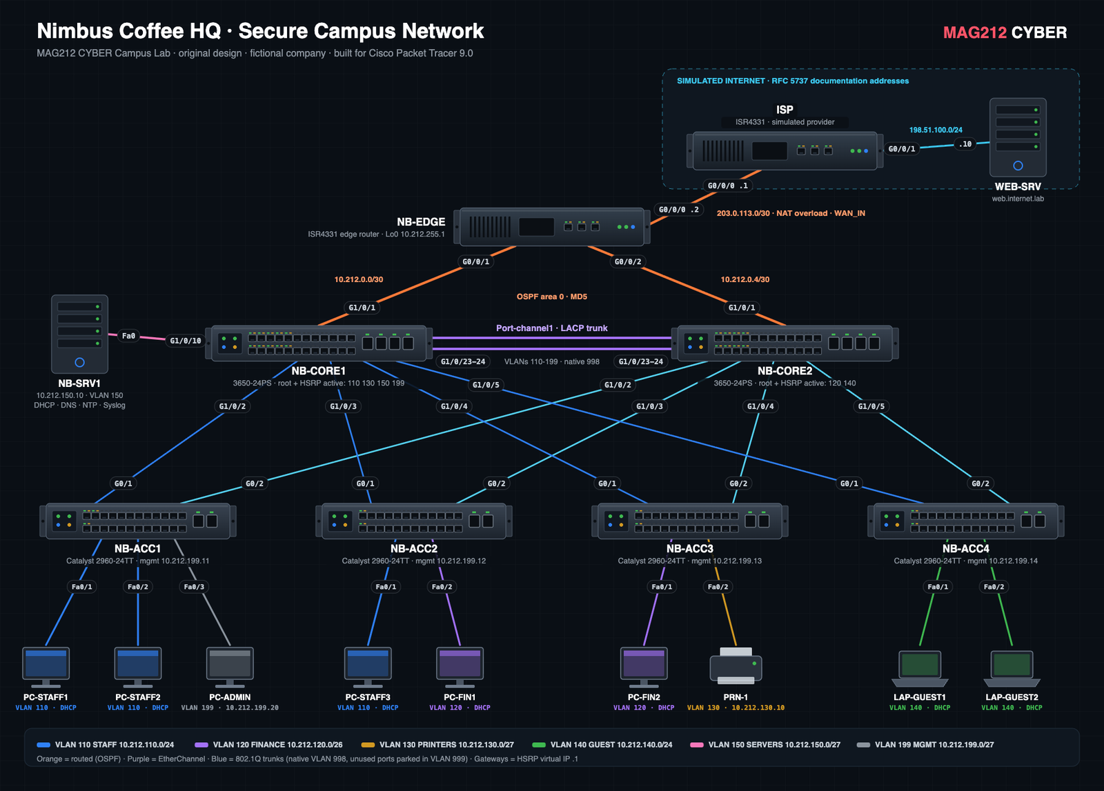
Original MAG212 CYBER design and artwork. Click to open full size. Level: intermediate (CCNA) · Time: 3 to 4 hours · Needs: Cisco Packet Tracer 9.0 (free) on macOS, Windows or Linux.
1 · Design: decide before you click
Good networks are designed on paper first. Nimbus Coffee’s head office has staff, a finance team, shared printers, guest Wi-Fi visitors and a small server room. The requirements are:
- Separation: each group in its own VLAN, so a problem or an attacker in one cannot easily reach the others.
- No single point of failure between users and the Internet: two core switches, two uplinks per access switch, two routed links to the edge.
- Central addressing: one DHCP server for every user VLAN.
- Least access: guests get the Internet only; only staff and finance can print; only the management VLAN can log in to network devices.
The architecture: a two-tier “collapsed core”
Large campuses use three layers (access, distribution, core). A single building usually does not need a separate core, so the core and distribution roles are combined into one redundant pair of multilayer switches. That is what Nimbus HQ uses:
- Edge: NB-EDGE connects to the provider, translates private addresses with NAT and gives the inside a default route.
- Core/distribution: NB-CORE1 and NB-CORE2 route between VLANs, act as the default gateways (with HSRP), and are the Spanning Tree roots.
- Access: NB-ACC1 to ACC4 connect the users. This is where most security controls live.
The VLAN and IP plan
One simple rule makes the plan easy to remember and troubleshoot: the third octet equals the VLAN ID. VLAN 110 is 10.212.110.0, VLAN 140 is 10.212.140.0, and the gateway is always .1. Subnet sizes follow the need (VLSM): finance gets a /26 (62 hosts), printers a /27.
| VLAN | Name | Subnet | Gateway | Primary core | Addressing |
|---|---|---|---|---|---|
| 110 | STAFF | 10.212.110.0/24 | 10.212.110.1 | NB-CORE1 | DHCP |
| 120 | FINANCE | 10.212.120.0/26 | 10.212.120.1 | NB-CORE2 | DHCP |
| 130 | PRINTERS | 10.212.130.0/27 | 10.212.130.1 | NB-CORE1 | Static |
| 140 | GUEST | 10.212.140.0/24 | 10.212.140.1 | NB-CORE2 | DHCP |
| 150 | SERVERS | 10.212.150.0/27 | 10.212.150.1 | NB-CORE1 | Static |
| 199 | MGMT | 10.212.199.0/27 | 10.212.199.1 | NB-CORE1 | Static |
| 998 | NATIVE-UNUSED | Native VLAN on every trunk. No hosts, no gateway. | |||
| 999 | PARKING | Every unused port lives here, shut down. | |||
Routed links: 10.212.0.0/30 (EDGE–CORE1) and 10.212.0.4/30 (EDGE–CORE2). Loopbacks 10.212.255.1 to .3. The ISP side uses 203.0.113.0/30 and the “Internet” 198.51.100.0/24, both reserved for documentation by RFC 5737.
Redundancy that actually works
Two core switches only help if they agree on who does what. Each VLAN has one primary core that is both the Spanning Tree root and the active HSRP gateway: NB-CORE1 for 110, 130, 150 and 199, NB-CORE2 for 120 and 140. Aligning them means traffic takes the shortest path and the load is shared. Each core watches its own uplink to the edge (HSRP tracking). If that link fails, its priority drops from 105 to 95, below its peer’s 100, and the other core takes over the gateway within seconds.
2 · Build it in Packet Tracer
- Install: create a free Cisco Networking Academy account and download Packet Tracer 9.0. On Apple Silicon Macs it runs through Rosetta 2; if macOS blocks it, use System Settings → Privacy & Security → Open Anyway.
- Place the devices: two ISR4331 routers (ISP, NB-EDGE), two 3650-24PS (cores), four 2960-24TT (access), two Servers, six PCs, two Laptops and a Printer. Name each one as in the diagram.
- Cable: use Copper Straight-Through and choose every port yourself, exactly as labelled in the diagram. The full cabling table is in the lab’s README.
- 3650 tip: if a 3650’s ports stay red, open its Physical tab and drag a power supply into the empty slot.
- NB-EDGE tip: the ISR4331’s third port (Gi0/0/2) is an empty SFP slot. Before cabling, open NB-EDGE → Physical and drag a GLC-TE copper module into the GE 0/0/2 slot.
3 · Configure, one layer at a time
The download contains one complete config per device. Paste them in order (ISP, EDGE, CORE1, CORE2, then the access switches), but read each stage below first so you know what every block does.
log on ACL lines and login quiet-mode), so the configs leave them out; the README lists every fix we needed.Stage 1: VLANs and trunks
Every switch learns the VLAN names. Trunks carry only the VLANs they need (here NB-ACC4 needs only GUEST and MGMT), use an unused native VLAN, and never negotiate.
vlan 140
 name GUEST
interface GigabitEthernet0/1
 switchport mode trunk
 switchport nonegotiate
 switchport trunk native vlan 998
 switchport trunk allowed vlan 140,199
Stage 2: EtherChannel between the cores
Two links between the cores are bundled with LACP into Port-channel1, so they act as one fast link and Spanning Tree does not block one of them.
interface Port-channel1
 switchport mode trunk
interface range GigabitEthernet1/0/23 - 24
 switchport mode trunk
 channel-group 1 mode active
In our Packet Tracer build the bundle first showed Po1(SD). Removing and re-adding channel-group 1 mode active on both cores brought it up; afterwards save every device and use Power Cycle Devices once so all switches start with clean MAC tables.
Stage 3: Spanning Tree roots
On NB-CORE1 (NB-CORE2 is the mirror image):
spanning-tree mode rapid-pvst
spanning-tree vlan 110,130,150,199 root primary
spanning-tree vlan 120,140 root secondary
Stage 4: Gateways with HSRP, plus DHCP relay
Each core has its own address in the VLAN (.2 and .3) and they share the virtual gateway .1. ip helper-address forwards DHCP requests to the server in VLAN 150.
interface Vlan110
 ip address 10.212.110.2 255.255.255.0
 standby version 2
 standby 110 ip 10.212.110.1
 standby 110 priority 105
 standby 110 preempt
 standby 110 track GigabitEthernet1/0/1
 ip helper-address 10.212.150.10
Stage 5: Routing (OSPF) and Internet access (NAT)
The cores and the edge share routes with OSPF over authenticated links. The edge has a static default route to the ISP and advertises it inside with default-information originate. NAT overload lets every inside device share one public address.
router ospf 1
 router-id 10.212.255.1
 passive-interface default
 no passive-interface GigabitEthernet0/0/1
 no passive-interface GigabitEthernet0/0/2
 default-information originate
ip route 0.0.0.0 0.0.0.0 203.0.113.1
ip nat inside source list NAT_INSIDE interface GigabitEthernet0/0/0 overload
Stage 6: The server and the hosts
NB-SRV1 is set up in Packet Tracer’s graphical Services tab: DHCP pools for STAFF, FINANCE and GUEST (each with the right gateway), DNS, NTP and Syslog. The README lists every value. Then set every PC and laptop to DHCP, and give PC-ADMIN and the printer their static addresses.
4 · Secure it: think like an attacker
Security is applied in layers. For each control, ask what attack it stops:
| Attack or risk | Control in this lab | Where |
|---|---|---|
| Someone plugs into a spare wall port | Unused ports shut down and parked in VLAN 999 | All switches |
| A device pretends to be a switch (VLAN hopping, DTP) | switchport nonegotiate, unused native VLAN 998, pruned trunks | All trunks |
| A rogue switch tries to take over Spanning Tree | PortFast with BPDU guard on user ports, root guard on core downlinks | Access / core |
| A laptop floods the switch with fake MAC addresses | Port security: maximum 2 MACs, sticky, violation restrict | Access ports |
| A rogue DHCP server hands out a fake gateway | DHCP snooping: only the uplinks are trusted | Access switches |
| ARP spoofing / man-in-the-middle | Dynamic ARP Inspection on the DHCP VLANs | Access switches |
| A guest sends fake HSRP messages to become the gateway | GUEST_IN accepts HSRP hellos only from the two real cores | Core, VLAN 140 |
| A guest reaches internal systems | ACL GUEST_IN: DHCP, DNS and the Internet only | Core, VLAN 140 |
| Anyone can reach the printers | ACL PRINTERS_OUT: staff and finance only | Core, VLAN 130 |
| Password guessing on network devices | SSH v2 only, local users, VTY ACL (MGMT VLAN only), timeouts; login block-for on the edge router | Every device |
| A fake router injects routes | OSPF MD5 authentication; user VLANs passive | Edge and cores |
| Spoofed private addresses from the Internet | ACL WAN_IN drops RFC 1918, loopback and other impossible sources | Edge WAN |
| No evidence after an incident | Central syslog and NTP time on NB-SRV1, timestamps in logs | Every device |
Know the limits of each control
- Dynamic ARP Inspection only trusts addresses it saw handed out by DHCP. That is why it is off on the printer and management VLANs (static addresses), and why you enable it after every PC has renewed its lease. A real network adds static bindings or ARP ACLs for fixed devices.
- WAN_IN is anti-spoofing, not a firewall. It drops impossible source addresses. What really keeps the Internet out is NAT overload, which has no inbound mappings, plus the VTY ACL. A real edge adds a stateful firewall.
- PRINTERS_OUT filters traffic routed into VLAN 130. It does not filter traffic the core switch sends itself (so a ping from a core still works), or traffic between devices inside VLAN 130. A production version would also allow only print ports (TCP 9100, 631, 515).
- Guests cannot ping even their own gateway: GUEST_IN blocks every 10.x.x.x destination. That is expected, not a fault.
- HSRP in other VLANs trusts the users in them. Real networks also add HSRP authentication.
- service password-encryption only hides passwords from shoulder-surfing (weak type 7). The real protection is
secret, which stores a hash. - OSPF MD5 is what Packet Tracer supports. On modern equipment prefer the SHA-based options your platform offers.
- NB-SRV1 is a single point of failure. It hangs off NB-CORE1 only: if that switch fails, new devices get no DHCP or DNS. Fixing it is the bonus exercise.
5 · Verify, then try to break it
A network is only finished when you have proved it works and proved the security controls block what they should:
show etherchannel summaryon a core: Port-channel1 is up with both links bundled.show standby brief: NB-CORE1 is active for 110, 130, 150, 199 and NB-CORE2 for 120 and 140.show ip ospf neighboron NB-EDGE: two neighbours in FULL state.- On PC-STAFF1:
ipconfigshows a 10.212.110.x lease, andhttp://web.internet.labopens in the web browser. - From LAP-GUEST1: the web works, but a ping to any 10.212.x.x address fails, by design.
- From PC-ADMIN:
ssh -l netadmin 10.212.199.2works. From PC-STAFF1 the same command is refused. - Break it: shut NB-CORE1’s uplink. Watch NB-CORE2 become the active gateway for every VLAN, and confirm PC-STAFF1 can still reach the web server.
- Attack it: connect a rogue DHCP server to a spare port and renew a PC. It still gets its address from NB-SRV1, because DHCP snooping drops the rogue’s offers.
- Bonus: remove the biggest single point of failure. Connect NB-SRV1 to both cores, or add a second server, and prove DHCP still works with NB-CORE1 switched off.
The README has 13 tests with expected results, plus a troubleshooting section.
Download the lab
Packet Tracer saves projects in its own .pkt format, which we do not distribute: building the network yourself is the exercise. All configs are for a simulator. Adapt and review them before using any idea on real equipment, and only work on networks you own or are authorised to manage.
Check yourself
1. Why is NB-CORE1 both the STP root and the HSRP active gateway for VLAN 110?
So traffic from VLAN 110 goes straight up the forwarding uplink to the switch that routes it, with no extra hop across the core link. Misaligned roles still work, but waste bandwidth and confuse troubleshooting.
2. What happens if NB-CORE1’s uplink to the edge fails?
HSRP tracking lowers its priority from 105 to 95, below NB-CORE2’s 100. With preempt, NB-CORE2 becomes the active gateway and users keep working.
3. Why is VLAN 998 used as the native VLAN?
Untagged frames on a trunk fall into the native VLAN. Using an empty VLAN that no host uses removes a VLAN-hopping path (double tagging) and stops untagged traffic from landing in a real VLAN.
4. Why are only the uplinks trusted for DHCP snooping?
Real DHCP replies only ever arrive from the cores, which relay them from NB-SRV1. Any DHCP offer arriving on a user port must be a rogue server, so the switch drops it.
5. Which device would you add next to remove the biggest single point of failure?
A second server (or connecting NB-SRV1 to both cores). Today NB-SRV1 hangs off NB-CORE1 only. If that switch fails, new devices get no DHCP or DNS. The edge router and the ISP link are also single points of failure.
Sources and further reading
- Cisco Campus LAN and Wireless LAN Solution Design Guide
- Cisco Guide to Harden Cisco IOS Devices
- Cisco: Operate and troubleshoot DHCP snooping
- Cisco: Troubleshoot Dynamic ARP Inspection and IP Source Guard
- Cisco Packet Tracer (Networking Academy)
- RFC 1918: private addresses · RFC 5737: documentation addresses
Original lab by MAG212 CYBER. The two-tier campus pattern itself is a standard industry design. Cisco, Catalyst and Packet Tracer are trademarks of Cisco Systems, Inc.; this lab is not affiliated with or endorsed by Cisco. More labs: Hands-on Labs.
MAG212 CYBER offers network and cybersecurity consultation, penetration testing with MAG212 Atlas, and security seminars for organisations around the world.